
Submitted by lexa on
The Preferences window is accessed via the File menu or by pressing Ctrl-P in main program window.
Available settings are grouped into three tabs:
- Display Options – for parameters that affect the data display but do not affect the raw values interpretation
- Data Processing – for parameters that affect the interpretation of the raw data
- Vendor Specific: raw processing parameters that specific to some vendor, or file format.
- Histograms – for histogram parameters and defaults.
- File handling for settings that affect the opening / processing of files
- Misc. Options – for parameters controlling the behavior of the program, such as window positions preservation etc.
- Over/Under Exposure – the parameters that control the display of the over- and underexposed areas.
The buttons at the bottom of the Preferences dialog behave in the same manner, whatever the current opened tab is:
- OK: closes the Preferences window, saves the preferences in the Windows Registry and applies them to the currently loaded image, if any.
- Cancel: closes the Preferences window without changing or saving the preferences.
- Apply: saves the modified preferences and applies then to currently open images; does not close the Preferences window.
- Reset Defaults: returns the Preferences window fields to their default values.
Display Options Tab
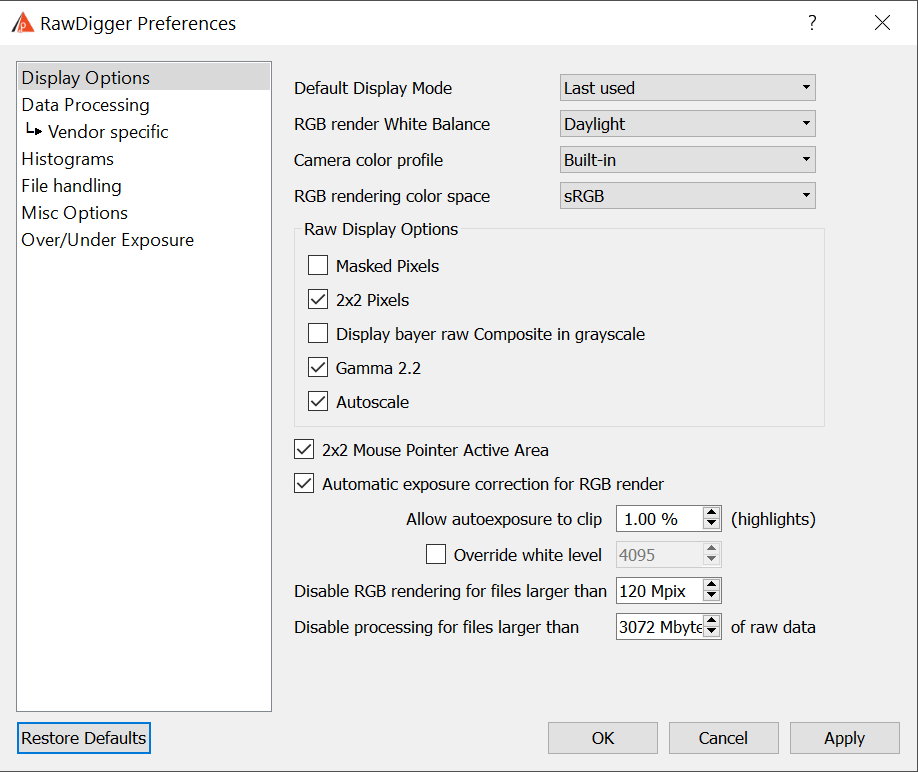
RawDigger Preferences window: Display Options Tab
The user preferences are arranged into the following groups:
- Default Display Mode – to set the view mode for the next file to be opened. The values are:
- Last Used – to use the same view mode as it was for the previous
- RGB render – to view the processed raw (if this mode is not available for some reason the program defaults to Raw composite view mode)
- Raw composite – to view RGB or Grayscale representation of all the channels in the raw file (please see below Display RGBG in grayscale mode)
- Raw Channel 1 .. Raw Channel 4 – the selected channel of the raw file will be displayed in grayscale.
- RGB Render White Balance: white balance used to create RGB rendering. This parameter has no influence on the representation of the raw data in information blocks for the image and the selected areas, neither in histograms nor in samples table.
Three values of White Balance are possible:- Daylight: balance for daylight (the balance parameters in the program are “built-in”, separately for each camera).
- As Shot: white balance as measured by the camera at the moment of shooting.
- Auto: white balance calculated from the raw data.
- Camera color profile: color profile used for RGB rendering. Again, this parameter does not affect raw data representation. Possible settings are:
- No profile (raw color) – switches off color conversion between camera color space and sRGB. For 4-color cameras (CMYG, RGBE, etc.) data in this mode can’t be displayed, however the file with “untouched out-of-camera colors” can be obtained through data export (see Data Export section).
- Built-in – use color profile provided within RawDigger
- Embedded in RAW – use color profile embedded in RAW if present. If no such profile exists, RawDigger will fallback to 'Built-in' mode.
- RGB rendering color space, choices are sRGB (default), Adobe RGB, Wide Gamut RGB, ProPhoto RGB.
RawDigger doesn't use color management, the output to screen is the direct one, the users of monitors set to emulate Adobe RGB or, more generally, wide gamut monitors may benefit from selecting Adobe RGB here; other options may turn useful if you want to display less saturated colors. - RAW Display Options: control of the raw mode display.
These parameters, same as the parameters for the RGB display, affect only the presentation of the image but not the “digital data”.- Masked Pixels: show the masked part of the camera sensor, which does not participate in the image formation (some manufacturing companies use the name Optical Black instead of Masked Pixels). This part of the sensor is masked from light; hence, in some cases it is possible to estimate the noise level in the deepest shadows, the banding level and to calculate the black level. The invisible (masked) pixels are not included in the raw image in some cameras.
- 2x2 Pixels: stretches each single-color (Bayer) pixel to the size of 2x2, making it possible to obtain an image more resembling the results after demosaicking. The figure below shows the result when this parameter is switched off:
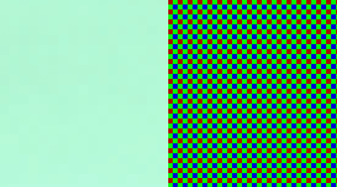
Fig. 6. White field shown in RAW mode with 2x2 Pixels set to ON (left) and OFF (right).
When the 2x2 Pixels mode is set to off, it is closer to reality for a Bayer sensor but moiré-prone on screen, unpleasant for the eye and the resultant picture is much darker.
In the figure above, the white field looks green, since the white balance in not used in the raw viewing mode and the green channel in most cameras is more sensitive than other color channels.
For the full-color and black-and-white RAW files (that is for the files with each pixel containing full information) this setting is ignored (processed as Off). - Gamma 2.2: sets gamma correction for raw data. Without this correction, the image looks dark.
- Autoscale: sets the automatic scaling of raw data to the display the brightness range. Without this scaling, the image in the raw viewing mode will look very dark.
- Display RGBG in grayscale - all pixels in the raw file will be displayed using grayscale instead of their «colors». This mode is incompatible with 2x2 pixels display mode.
If the file contains raw channels different from RGB(G), Raw Composite view mode will be substituted with grayscale, independent of the setting for Display RGBG as Grayscale.
For non-Bayer (full-color) RAW files this setting is always processed as Off.
- Mouse Pointer: parameters for displaying the raw value under the mouse cursor.
- 2x2 Active Area: if this option is on, the window with the values under the mouse cursor shows the pixel values in a 2x2 square around the pointer (the Bayer sensor contains pixels of all 4 channels in that square).
If this option is off, only the values corresponding to the pixel directly below the pointer are shown and the remaining three components are zero.
For the full-color and black-and-white RAW files (that is for the files with each pixel containing full information) this setting is ignored (processed as Off).
- 2x2 Active Area: if this option is on, the window with the values under the mouse cursor shows the pixel values in a 2x2 square around the pointer (the Bayer sensor contains pixels of all 4 channels in that square).
- Automatic exposure correction for RGB render: turns on the automatic brightness correction of RGB representation.
- Allow autoexposure to clip % (highlights) controls the relative amount of pixels that can be clipped when autoexposure is applied, and thus it controls the amount of lightening applied through autoexposure.
- Override white level: Allows to set white level used for rendering to user-specified value.
- Disable RGB rendering for files larger than NN Mpix: disables RGB rendering and RGB display for large files which are too large. You can set these limits as you wish, but for 32-bit systems it is impractical to render RGB for 40Mpix or larger files, because memory is limited on these systems.
- Disable processing for files larger than NN mbytes of RAW data: disables loading of too large RAW files to avoid memory overuse.
Data Processing Tab
Parameters in this tab do affect the representation of raw values in windows with statistical data, histograms and samples table.
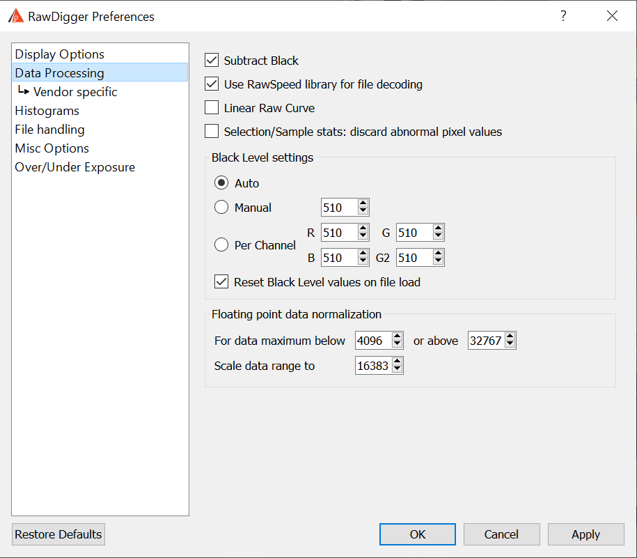
Raw Digger Preferences window: Data Processing Tab
The current version of RawDigger contains the following Data Processing parameters:
- Subtract Black: to subtract the “black level” (that is, the “dark current” value). The actual value to be subtracted is set in the Black Level block (see below).
- Use RawSpeed library for file decoding: this option controls the choice of raw decoding library, RawSpeed library or standard library. RawSpeed is significantly faster compared to standard but lacks some options and support for some raw formats.
If the decoding is set to RawSpeed: Linear Raw Curve option is Off and can't be switched to On. - Linear Raw Curve: to use the linear tone curve instead of the nonlinear (compression) one. This parameter is important only for cameras and data formats that use the tone curve specified in EXIF data for raw data linearization (e.g., a significant number of Sony cameras).
- Selection/Sample stats: discard abnormal pixel values: if this setting is on (checkbox set), statistics for Selection and Sample discards 10% of highest and 10% of lowermost pixel values to filter off dust, scratches, small specular reflections, and other target/sensor defects.
This mode is useful for creating measurements files from the shots of the profiling targets. It automatically filters off certain target and sensor defects to make measurement more meaningful.
This mode is available only in RawDigger Profile Edition. - Black Level: preferences for black subtraction mode.
These preferences can be formally attributed to the Data Processing block; however, since there are many customizable parameters here, this block is described separately.- Auto: the black level is set automatically. Depending on the file format, it will be either read from the EXIF data or calculated according to the black frame.
- Manual: the black level is set manually; identical values are set for all channels.
- Per Channel: the black level is set manually; different values for each channel are allowed.
- Reset Black Level values on File Load: when the next file is opened, the black level in the Manual and Per Channel input fields is set in accordance with the Auto variant but can be manually changed afterwards.
- For the automatically set Subtract Black Level, if BlackLevelRepeat* tag in DNG (or an analogous tag in files for Fuji X-Trans sensors) is present RawDigger takes the black level from large blocks (up to 64x64).
When manually setting the black level, (shared or by color channel) the aforementioned complex black level setting patterns are not used. - Floating Point Data Normalization groups:
- For data maximum below … or above … - if the actual data range _or_ the value of the maximum in the DNG file are out of this range.
- Scale data range to – then all the data numbers (pixel values) will be multiplied by the same coefficient, to make the actual maximum equal to value set in this field.
See section Processing of floating point data above for details.
Data Processing -> Vendor specific Tab
Settings related to specific data formats or manufacturers only (that is, Sony ARW2, Panasonic, PhaseOne, Sigma dp2 Quattro, Canon/Nikon sRAW/Small RAW)
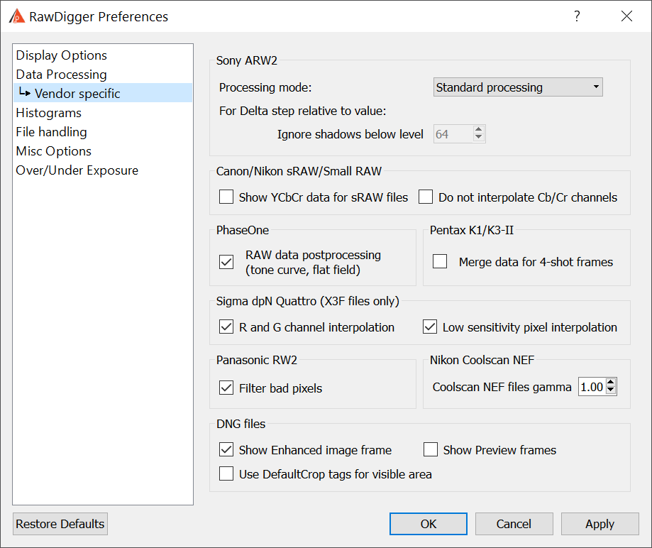
Raw Digger Preferences window: Data Processing -> Vendor specific Tab
- Sony ARW2 processing options – turns on special modes for processing lossy-compressed Sony ARW2 (cRAW):
- None (standard processing) – the data will be processed standardly
- Only base pixels – only the base pixel are used for output (the base pixels are the minimum and maximum for each color channel on a horizontal 32-pixel block). The values of other pixels ("delta-pixels") coded as rounded deltas from the minimum value in the block are set to zero.
- Only delta pixels – only the "delta pixels" are used for the output (with "base" minimum value added to them), base pixels are set to zero so as to output only the delta pixels.
- Delta pixels relative to zero – same as above but base minimum values are not added.
- Delta step relative to value – the output is the ratio of delta step to RAW value of the pixel. The units are pro mil (one per thousand). Those areas with large values of the ratio are the candidates for exhibiting posterization.
- Ignore shadows below level – do not compute / display Delta step relative to value for the image areas where the RAW value is lower than this setting (deep image shadows are characterized by relatively large step values and so those areas are obvious candidates for posterization; while excluding such areas from the display of posterization helps to avoid display congestion.
Turning on any mode except None forbids using the RawSpeed library.
Turning on the "Delta pixels relative to zero" mode turns off the use of RawSpeed and Subtract Black Level, and additionally turns on Linear Tone Curve.
- Show YCbCr data for Canon/Nikon sRAW files: switches off the conversion of YCbCr data contained in Canon sRAW/Nikon D4s small RAW (NEF Size S) to RGB. The brightness in channel Y is provided as is. For Canon cameras, Cb/Cr channels are shifted by subtracting 8192 to place achromatic “gray point” for Cb/Cr channels in the middle of the range.
Gamma correction is not applied to Cb/Cr channel data irrespective of the gamma setting in Display Options tab.
For YCbCr data histogram, the display is set to show X-axis in EV scale, that is logarithmic rule. The user can switch it to linear rule if desired.- Do not interpolate Cb/Cr channels data (Canon/Nikon sRAW)
The values for Cb/Cr channels in sRAW files are not defined for all pixels, but only in every second or every forth pixel. Before conversion to RGB the missing values for Cb/Cr channels are interpolated.
This option allows switching off such interpolation.
The option is available only together with the option Show YCbCr data for Canon/Nikon sRAW files.
- Do not interpolate Cb/Cr channels data (Canon/Nikon sRAW)
- Phase One RAW postprocessing: switches raw data processing on and off based on metadata in raw file (bad pixels map, additional tonal curves, etc.)
This setting does not affect the display in 'RGB render' mode. - Pentax K3-II
- Merge data for 4-shot frames - turns on merging of 4 subframes in 4-shot files
- Sigma dp2 Quattro options:
- R and G channels interpolation turns on the duplication of pixels in the R and G channels to form a 2x2 square.
- "Low sensitivity pixel interpolation" – turns on the normalization of pixels with lower sensitivity found in the R and G channels (in the dp2 Quattro camera, every 64th pixel in the R and G channels has a sensitivity lowered by about 2 stops. What these pixels are used for is currently not certain, possibly for exposure control in overexposed areas).
- Filter bad pixels on Panasonic files: this enables the filtering off for bad pixels in the raw files from Panasonic and some other cameras (the files contain zeros in the place of bad pixels).
- Nikon Coolscan NEF files gamma: allows to set gamma value to Coolscan files according to scanning settings.
- DNG Files
- Show Enhanced image frame: to allow the display of the image that corresponds to Adobe Camera RAW/Lightroom: Enhance image
- Show Preview frames: to allow the display of previews (usually those previews have low resolution) and Fast load data
- Use DefaultCrop tags for visible area – crop ActiveArea using DefaultCropOrigin/DefaultCropSize tags.
Histograms Tab
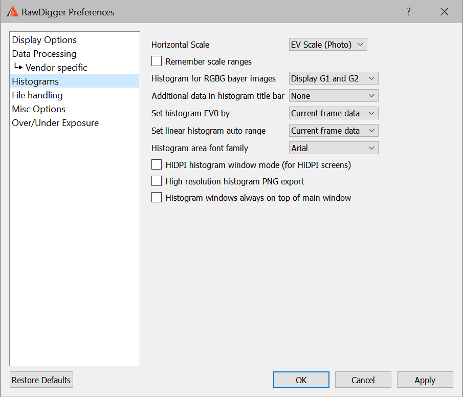
RawDigger Preferences window: Histograms Tab
- Histogram Scale – sets the horizontal scale for histogram window:
- Last Used – the histogram is shown with the settings from the previous
- EV Scale (Photographic) – photographic EV scale will be used
- Linear Scale – linear scale will be used.
- Remember scale ranges: to store the settings for the histogram window (range of values, grid on vertical and horizontal axis).
If this option is on the very last change made to any of histogram windows will be stored.
The settings stored here will be used when opening new histogram windows. Any change of parameters in one histogram window does not affect other histogram windows. - Histogram for RGBG bayer images – controls the number of per-channel histograms for regular Bayer-type 2x2 raw data (2 green, 1 red, and 1 blue in a 2x2 pixel square):
- Display G1 and G2 – separate histogram for each of green channels are displayed.
- G1 only – only the histogram of the first green channel is displayed; the histogram for the second green channel is omitted.
- Average G1 and G2 – an averaged histogram is displayed:
- Bar heights – average between 2 green channels.
- Statistics minimum and maximum – absolute minimum and maximum of the data collected from both green channels.
- Number of unique values – the number of unique values found in the green channel where it is larger.
- Number of of pixels – an average between both green channels.
- Additional data in Histogram title bar – controls the display of additional shooting information on the title bar of the histogram window
- None – no additional data is displayed.
- Exposure data – shutter speed, lens aperture, and ISO speed are displayed.
- Camera model – the make and the model of the camera are displayed.
- Exposure & Camera – both exposure data and camera model from previous is displayed.
- Set Histogram EV0 by – sets the choice of the maximum value that is used for automatic calculation of midpoint (EV0). EV0 is calculated as 3 stops below the chosen maximum:
- Current frame data – maximum value found in the currently opened frame is used.
- Camera data range – maximum value is determined by the raw data bit width (theoretically possible range). (Some cameras will not use the whole range; for some cameras the range changes with the change of ISO speed setting).
- Set linear histogram auto range – sets the choise of the data scale used in histogram linear mode:
- Current frame data – maximum value found in the currently opened frame is used.
- Camera data range – maximum value is determined by the raw data bit width (theoretically possible range). (Some cameras will not use the whole range; for some cameras the range changes with the change of ISO speed setting).
- Histogram area font family – sets font used for graphics histogram area (axis values, statistics, etc).
- HiDPI histogram window mode – doubles the resolution of the histogram window display. This mode is recommended primarily for HiDPI monitors used with Apple Mac.
- High resolution histogram PNG export – doubles the resolution when exporting the histograms to PNG files.
- (Windows Only) Histogram windows always on top of main window – in this mode the histogram windows are always on top of the main program window.
File Handling Tab
This tab contains settings that affect the opening / processing of files
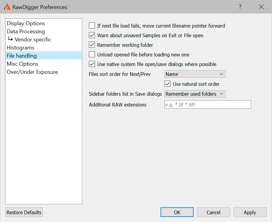
- If next file load fails, move current filename pointer forward – this setting controls RawDigger behavior if next file (via Menu – File – Next/Prev file, or via Ctrl-Arrow keys) load fails for whatever reason. With the checkbox on, RawDigger will allow subsequent Next/Prev file actions to count from new (failed to load) current file.
- Warn about unsaved Samples on File Open/Exit.
To switch unsaved sample on/off data warning. - Remember Working Folder: to set the folder (directory) of the last opened raw file as working; next Open/Save dialogs will start in that working folder.
The setting is in effect for all consequent RawDigger runs, until re-defined. - Unload opened file before loading new one: if this setting is active the file that is currently opened will be closed to free the memory.
This mode is useful while processing very large (40-50Mpix and more) files.
If this setting is active all samples and selections are not inherited for the new file. - Use native system file open/save dialogs where possible – open/save file dialogues (except those dialogs with additional parameters), will use “native system dialogs” (the ones that are like those in Windows Explorer/Mac Finder).
- File Sort order for Next/Prev: to set the sorting order for Next file/Prev file operations:
- Name: sort by the file name.
- Modify time: sort by the file time stamp.
- Size: sort by the file size.
- Unsorted: files are sorted by the operational system, usually in the order they arrived in the directory.
- Use natural sort order – when sorting by filename, a natural sort order will be used with numericals (e.g., the order of files will be a1.ext a2.ext a10.ext). When this is turned off, an alphabetic sort order will be used (a1.ext a10.ext a2.ext).
- Sidebar folders in “Save…” dialogs: The user can now control the set of folders, which is displayed in the Sidebar of the “Save…” dialogs (that is, export of RAW data and saving the measurement tables). The choices are:
- Remember used folders: to display the list of previously used folders ("traditional" behavior).
- Standard list: include only Desktop, Documents, Pictures, TEMP, and Home folder.
- Home Folder only
- Additional RAW extensions – to add extensions to the list of the file extensions known to RawDigger by default. These additional extensions will be allowed for Open and Prev/Next raw file open operations. The list of additional extensions is of the form of file name masks separated with a space, like *.tif *.bin.
Misc. Options Tab
This tab contains the settings that affect the program’s behavior, but do not directly affect data processing or data display.
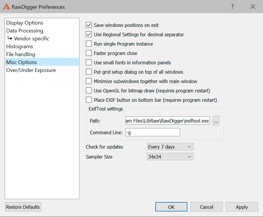
Raw Digger Preferences dialog, Misc. Options tab
- Save windows positions on exit: to store the position and dimensions of all the program windows on program exit. The positions and dimensions of the windows will be restored upon next program start; that is – when the program starts only the main window is opened, but when additional histogram and samples windows are created they will be positioned and sized according to the saved settings.
- Use Regional Settings for decimal separator: Enables the use of the System Regional Settings to set the decimal separator. (Control Panel - regional Settings - Country). If those are set to use comma as the decimal separator - semicolon will be used as the field delimiter in CSV files.
If the "Use Regional Settings" is turned off a period will be used as the decimal separator. - Run single Program Instance (Windows only): to prevent running multiple copies of the program. While in this mode,
- If a new RawDigger process is started while the raw file name is passed to RawDigger as a command line parameter the file will be opened in the already existing program window.
- New RawDigger process will be immediately terminated after that.
- Faster program close (Windows only) – turns on faster program exit (resources are not released, operating system will do it for us).
- Use small fonts in information panels – decreases the font size and shrinks the gaps between the informational panels in the upper part of the program window. Useful for the lower resolution displays.
- Put grid setup dialog on top of all windows (Profile edition only) – makes Grid Setup window floating other all windows of all programs running.
- Minimize subwindows together with main window – If this setting is enabled, minimizing the main program window will also cause minimization of all other windows.
- Use OpenGL for bitmap draw – when this setting is turned on, OpenGL will be used to display images. This may work faster on computers with old CPUs.
- This settign is unavailable in Legacy versions.
- Place EXIF button on bottom bar – cleans space in metadata area by moving EXIF button on the program bottom bar (this setting will take effect after program restart).
- ExifTool Settings: path to ExifTool utility and parameters to control it:
- Path: the path to ExifTool executable module. The value is set during the install of RawDigger, but if you have a version of ExifTool that you prefer (for example, a more recent one) you can set the path to point to that version.
- Command Line: parameters for ExifTool command line. RawDigger will pass those parameters to ExifTool adding –h for HTML output.
- Check for updates: this parameter schedules the checks for updates - at each program launch or once in every 1-3-7-15-30 days.
- Sampler Settings: sampler tool preferences
- Sampler Size: selection of the sampling size area from a list (2x2, 6x6, 10x10, 18x18, 34x34, 66x66).
If you need a nonstandard sampling size, you can perform manual selection (Selection) and then convert it to a sample (menu item Selection -> Convert Selection to Sample).
Sampler Size Control is available only in Research и Profile editions of RawDigger.
- Sampler Size: selection of the sampling size area from a list (2x2, 6x6, 10x10, 18x18, 34x34, 66x66).
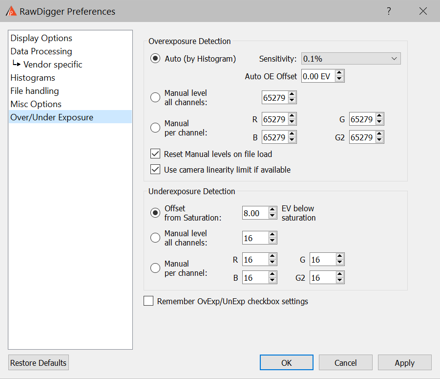
Over/Under Exposure tab
This tab allows adjusting the settings that control how the areas of underexposure and overexposure are defined.
- Overexposure Detection: to control how the overexposure (saturation, blow-out) are defined
- Auto (by Histogram): overexposure is determined by the analysis of the peaks on the histogram using the area of extreme highlights.
- Sensitivity – the width of the area designated as overexposure
- Value on percent (from the whole range of values offered by the camera) - sets the search radius for the sharp histogram peak.
- Full Well limited camera - turns on an alternative algorithm of finding overexposure by the "fuzzy hump". This mode is intended for use with cameras, where the target RAW-values are not limited by ADC but use close to the whole range of the sensor values.
- Auto OE Offset – lets you change the values set by the automatic algorithm. The shift must be set in photographic stops; negative shift lowers the boundary for detecting overexposure, positive shift raises it.
- Manual level, all channels: to set the single overexposure value for all color channels.
- Manual per channel: to set overexposure levels for each color channel independently.
- Reset Manual levels on file load: to use automatically computed (Auto, by histogram) levels when loading a new file; the computed levels will be set into the “manual” fields and used as such.
- Use camera linearity limit if available: If this setting is on, for the cameras with recommended raw maximum white value contained in metadata this value takes precedence when detecting overexposure.
- Underexposure Detection: the settings which control how the areas of underexposure are determined
- Offset from Saturation: the underexposure level is defined as an offset (in EV) relative to overexposure (saturation) level.
If while setting the level of overexposure the shift from the automatic level was used, this same shift will be used for the underexposure boundary. - Manual level, all channels: to set the single underexposure level for all color channels.
- Manual, per channel: to set the underexposure levels independently for each color channel.
- Offset from Saturation: the underexposure level is defined as an offset (in EV) relative to overexposure (saturation) level.
- Remember OvExp/UnExp checkbox settings: to store the settings for over- and underexposed areas display.
Support of non-standard cameras
RawDigger can be used for the display and analysis of images from “engineering” cameras, which are saved in the form of “sensor data dumps” without any other additional metadata.
A series of such cameras are already directly supported by the program (RawDigger contains an internal table with the necessary data); to support other (arbitrary) sensors, one has to add a description of the structure of the sensor’s data into the Windows Registry (on Windows) or OS X defaults (on Mac OS X).
To do this one must:
Windows: prepare a registry-script with content similar to the following:
[HKEY_CURRENT_USER\Software\LibRaw LLC\CustomCameras]
"Camera01"="24096096,4008,3006, 0, 0, 0, 0,0,148,0,0,Dalsa, FTF4052C 4:3,0"
And run it in Windows Explorer.
OS X: run a command in the Terminal, similar to the following one-liner:
defaults write com.libraw-llc.CustomCameras "Camera01" "24096096,4008,3006, 0, 0, 0, 0,0,148,0,0,Dalsa, FTF4052C 4:3"
In both cases:
Camera01 (or Camera02 … Camera64) – the “number line” in the table, up to 64 records of this type are supported.
The line “24096096,4008,3006, 0, 0, 0, 0,0,148,0,0,Dalsa, FTF4052C 4:3,0” defines the format of the camera’s data and consists of 14 fields separated by commas (a note for engineers: the format of this line is completely analogous to the line in the “sensor dump” table’s description in dcraw.c with the one difference being that the CFA filter’s format is set in base 10):
- The exact size of the file in bytes (in this example – 24096096). This is the only criterion by which RawDigger recognizes a data “format”, files of a different size will be ignored.
- The width of the sensor in pixels. Put the entire width, including the “black frame” in this field.
- The height of the sensor in pixels, including the black frame.
- The width of the black frame at the left edge of the sensor (in pixels)
- The width (height) of the black frame at the top.
- The width of the black frame at the right edge.
- The width (height) of the black frame at the bottom.
- Additional parameters for the file decoding subprogram (see below).
- The Bayer filter CFA format, with the byte field taking one of the following values:
- 22 – BGGR
- 97 – GRBG
- 73 – GBRG
- 148 – RGGB
- 180 - GMYC
- The amount of unused bit data (for example, if 14-bit data is recorded in a 16-bit format)
- Additional metadata, bit mask.
- Bit 0 – find a .JPG file with the same name and read the EXIF data from it.
- Bit 1 – filter (average neighbors) for pixels with values of zero
- Bits 2-4 – the orientation of the image (0=do not rotate, 3=180, 5=90CCW, 6=90CW)
- Camera manufacturer
- Camera model
- The offset of the beginning of the sensor data from the beginning of the file (the value range is 0-65534, the special value 65535 means that “the rows are going in the opposite direction”).
8, 10, 12, and 16-bit data formats are supported, the amount of bits is calculated as (the size of the file minus the offset from the beginning of the data)/number of pixels.
Depending on the bit-ness of the data, the 8th field (“additional parameters for the file decoding subprogram”) can accept the following values for 10-bit data:
- 1: “4 pixels in 5 bytes” packing is used
- 0: “6 pixels in 8 bytes” packing is used
Last comments